GD&T Callouts That Suppliers Routinely Misinterpret
Suppliers misread feature control frames, datum order, and modifiers before production even starts.
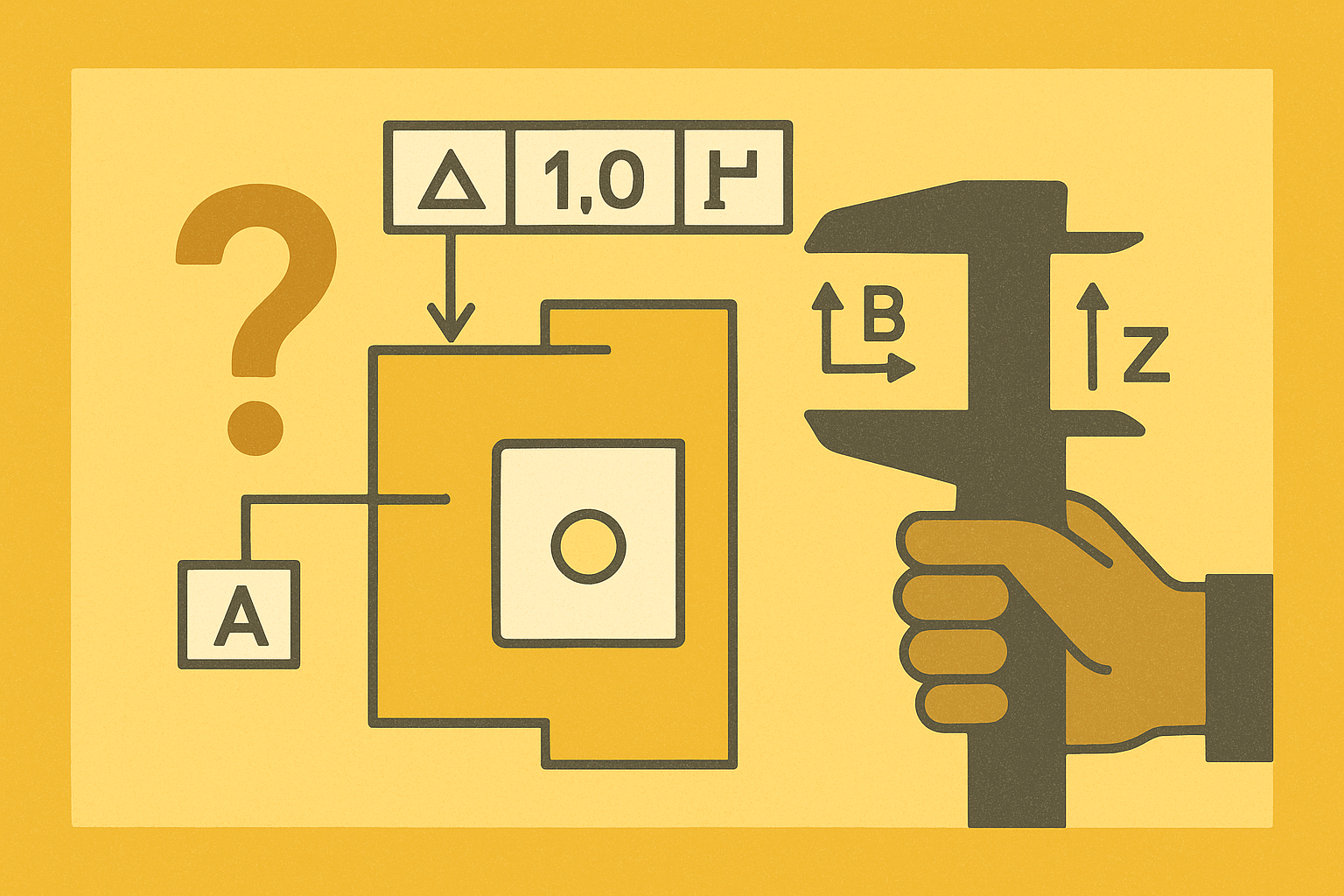
A part comes back wrong, and the first instinct is to blame the shop. That instinct is usually misplaced. GD&T is the most standardized method for communicating part geometry in North American manufacturing, and ASME Y14.5 is the dominant standard that governs it across the United States and much of North America. Even so, machinists and quality engineers misread feature control frames, datum references, and modifier symbols every day. Standardization moves where the room for interpretation hides, tucked inside a modifier compartment or a datum order that two trained readers can honestly disagree about.
The drawing released to a supplier sets the standard for every part built from it. If a callout carries two valid readings, both readings will appear in a production run, usually on different lots and usually months apart, and the customer's incoming inspection usually catches it. The drawing left a gap that nobody closed before the part was ever quoted, not a training failure on the shop floor.
Misreading the feature control frame before machining
Three upstream reading habits account for most of the downstream trouble: ignoring where the leader line actually attaches, treating the three datum references as if their order doesn't matter, and skipping past the modifier compartment without applying it.
Reading a feature control frame left to right is correct, but it's not enough on its own. The leader line tells the reader what the tolerance actually governs. A leader line aimed at a surface makes the tolerance apply to that surface. Align it with a dimension line on a feature of size, and the tolerance applies to the axis or center plane instead. That distinction has to be caught before a single cut is made, or the setup built from it is wrong.
Datum order carries the same weight. The primary datum constrains the most degrees of freedom, the secondary constrains more, and the tertiary picks up what's left. That order is a machine setup instruction. The measurement setup follows directly from that order. A common shop-floor error treats all three datum references as equally important, which produces an inspection result that looks clean but was measured against the wrong reference frame.
The modifier compartment changes the actual number, not just the way it reads. Material condition modifiers add bonus tolerance as a feature's size moves away from its stated limit. Reading the tolerance value without accounting for the modifier produces a number that is either too tight or too loose for what the drawing actually allows.
All of this converges at the CMM. If the datum setup on the coordinate measuring machine doesn't match the functional datum structure on the blueprint, every inspection result from that setup is invalid, no matter how accurate the machine is. A part can pass a supplier's in-house check and still fail a customer's incoming inspection, because the two sides built their datum setups on different assumptions about the same print.
True position with MMC modifiers (the highest-frequency misinterpretation)
True position is where the most common and the most expensive misreads happen, and it starts with a basic geometric mismatch. Coordinate tolerancing builds a square tolerance zone. True position builds a cylindrical one. A hole can sit within its allowed X deviation and its allowed Y deviation individually and still fall outside the cylindrical zone that true position actually defines. The reverse also happens: a feature that looks like it fails a coordinate check can sit comfortably inside the cylindrical zone once it's measured correctly.
The correct math takes the resultant deviation, not the two axes separately: the resultant diameter equals two times the square root of X squared plus Y squared. Plenty of shop-floor workflows skip that step and check X and Y against the print independently, which produces the wrong accept or reject decision in both directions.
The MMC modifier turns this from a math problem into a cost problem. Maximum material condition grants bonus tolerance as a feature departs from its tightest allowed size, and that bonus can cut scrap rates on hole patterns significantly. Specify RFS (regardless of feature size) on a clearance hole for a bolt or screw instead, and the machinist has to hold tight position no matter what size the hole actually comes out at. The fastener going through that hole never needed that level of control, which drives up cost for no functional return. Putting MMC on that same clearance hole gives the machinist extra positional tolerance exactly when a hole drifts toward its upper size limit, which happens naturally as drills wear through a production run. That's tolerance the callout can hand over for free, and a drawing that specifies RFS instead is paying for precision nobody asked for.
A second, structural mistake compounds this one: adding a separate perpendicularity callout to a hole that already carries a position tolerance relative to the same primary datum. True position already controls perpendicularity to that primary datum within its own zone. A perpendicularity callout layered on top doesn't add control; it adds a second requirement that inspectors and machinists end up reconciling in different ways. Two shops can build to the same print and defend two different parts.
Composite position tolerances (upper and lower segment confusion)
Composite position tolerancing takes the true position symbol and splits it into two stacked segments, and the trouble here has nothing to do with the symbols being unfamiliar. The two segments look almost identical on the print, and they control two completely different things. Most shops learn one interpretation and apply it to both segments, which is exactly backward half the time.
The upper segment is a location control. It governs where the entire feature pattern sits relative to the datums listed in that segment. The lower segment does something narrower: it controls only the spacing between features within the pattern, not the pattern's location relative to the datum scheme. If a datum does repeat in the lower segment, it constrains the pattern's orientation relative to that datum, but it still doesn't pin down location the way the upper segment does. Both segments, and the datum references tied to each one, have to be read and populated correctly for the part's functional intent to survive the trip from print to machine.
The failure plays out in two directions. A supplier who reads both segments as location controls holds the pattern to a tighter standard than the lower segment ever intended, and rejects parts that would have assembled just fine. A supplier who reads both segments as spacing controls ignores the datum location requirement in the upper segment entirely, and accepts a pattern that's shifted too far from where it's supposed to sit. Errors in GD&T application lead to part rejection, production delays, and functional failures, and composite position disputes are a frequent trigger for incoming inspection rejections that the print, read correctly, never actually called for.
Profile of a surface without explicit datums (the callout that silently changes meaning)
Profile of a surface does more jobs than almost any other GD&T symbol, and that flexibility is also its biggest liability. Whether the feature control frame carries datum references changes what the callout means at a structural level, not a cosmetic one. Without datums, it's a form control. With datums, it becomes a location and orientation control at the same time, applied simultaneously.
The numeric misread is the easiest version to catch and the most common to miss. A profile tolerance of 0.5 mm defines a zone that's 0.5 mm wide in total, split around the true profile: 0.25 mm of room outside the nominal surface, 0.25 mm inside it. The frequent mistake reads that 0.5 as if it were written ±0.5, which doubles the allowed variation. A surface machined to that doubled window can pass a shop's own internal check and still fail first article inspection once a customer measures it against the actual 0.5 mm total band.
The deeper structural issue sits with the datums themselves. Profile without datum references lets the surface float in space as long as its form stays inside the bilateral zone around the true profile. Adding datum references to that same symbol anchors the zone to the datum reference frame: the surface can no longer float, because its location and orientation are now locked down along with its form. Two feature control frames that look nearly identical on paper are two entirely different requirements. A supplier who treats a datum-referenced profile as nothing more than a form check will build parts that measure fine in isolation and fail the moment they meet the next part in the assembly.
The unequally disposed modifier stacks a second risk on top of the first. An unequally disposed zone can leave as little as 0.1 mm of material on the side of the surface that actually matters functionally. An estimator who assumes a standard, evenly split bilateral zone prices and machines to the wrong split, and ends up with a part that sits inside the total tolerance band on paper while violating the one side of that band the design actually depended on.
Datum reference ambiguity and unmachinable datums
Every error described so far happens at the level of a single symbol. One error sits beneath all of them and produces the rest: a callout can be read exactly right and still produce a bad part, because the datum it points to can't be reliably established on the shop floor or at the CMM. The reference frame exists on the drawing. It doesn't exist yet on the fixture or the inspection table.
Picking a datum off a cast surface, a rough saw-cut edge, or an internal feature that can't be probed until something else is machined first is a drawing mistake. It forces the supplier to guess which physical surface best approximates what the print intended, and two capable suppliers will land on two different surfaces. The fix sits on the design side: the primary datum should be a machined face, large enough to seat stably on a fixture, and the secondary should be a long enough edge to orient the part the same way every time.
Multi-setup datum drift is the process-side version of the same problem. A part machined on one side, unclamped, flipped, and reclamped for a second operation picks up tiny variations in how it seats the second time. Those variations shift new features relative to the original datum scheme, and the error accumulates with every additional setup. That's a predictable consequence of a datum scheme that demands multiple setups, not a sign of sloppy work on the supplier's end. Consolidating operations onto five-axis CNC equipment and keeping critical-to-quality features tied to a single, consistent datum scheme are the real engineering countermeasures, not tighter tolerances layered on top of an already fragile setup.
Both problems collapse a distinction that should hold: the datum feature is the physical surface on the part, and the datum itself is the theoretically exact plane, axis, or point derived from that surface. Confusing the two is a leading cause of disputes between suppliers and buyers who each measured the part correctly, against two different understandings of what the reference actually was.
Flatness and form tolerances applied without process or material context
Flatness, straightness, circularity, and cylindricity get specified, routinely, at values that are either impossible to verify functionally or indefensible economically once the part's material, size, and process are accounted for. When that happens, the mistake is in the drawing, not in how the supplier executed it.
Flatness is the cleanest example. A tight flatness callout on a large plate, with no functional justification and no notes on stress relief or fixturing, can make the part expensive to hold within tolerance or nearly impossible to hold. Tolerances that tight often require face milling followed by surface grinding or lapping: separate setups, separate equipment, and real lead time added to the job. A supplier isn't going to volunteer that information unless the drawing itself forces a design-for-manufacturing conversation before the quote goes out.
A related blueprint error compounds the cost. Form tolerances are self-contained and reference no datum. Adding a datum reference to a flatness callout is a drawing error on its face, and some suppliers will try to satisfy both the form control and that extra, unnecessary datum reference at once, which produces an inspection result that doesn't actually satisfy either requirement cleanly. Tight tolerances applied without weighing their manufacturing impact drive up cost, slow down the job, and raise the odds of rejecting a part that would have functioned perfectly well at a looser, cheaper, and entirely defensible number.
Sources
- Apparatus and method for determining the minimum zone for an array of features with a true position tolerance
- Method and system for assisting a user taking measurements using a coordinate measurement machine
- Analysis Modeling > Tolerances > GD&T > Composite GD&T
- Profile of a Surface GD&T: How to Read & Measure