BOM Readiness Checklist Before Sending RFQs
A complete BOM prevents supplier guesswork and cuts weeks from your sourcing cycle.

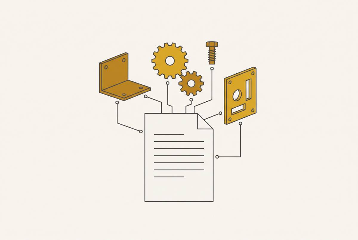
An RFQ is a narrow instrument. It asks a supplier for price and delivery against exactly what you send them, nothing more. Sending a BOM with gaps doesn't get you one bad quote back. You get several incomparable ones, because each supplier fills the gaps differently, guessing at tolerances, materials, and finish in ways that make apples-to-apples comparison impossible. This piece lays out what a genuinely quote-ready BOM looks like, process by process, before it ever leaves your desk.
The cost of skipping this work isn't abstract. The Hackett Group's 2025 research found that digital, world-class procurement teams run sourcing cycles 24% shorter and requisition-to-PO cycles 58% shorter than their peers, largely because they apply structured evaluation upfront instead of catching problems mid-cycle. Practitioner guidance backs this up: roughly half of total RFQ cycle time should go into upfront prep, meaning BOM validation, stakeholder alignment, and supplier criteria, before a single quote request goes out. If you skip that half, you pay for it later in clarification emails and re-quote rounds. With ISM reporting average production material lead times of 85 days in July 2025 and 84 days in August, a multi-week clarification cycle eats directly into schedule you don't have. It's schedule you don't have.
What BOM readiness means, and what it doesn't
Readiness isn't one fixed condition. It depends entirely on who's about to read the BOM and what they need to do with it.
Purchasing needs preferred vendors, manufacturer part numbers, cost targets, lead times, and approved alternates. Manufacturing needs drawings attached, revisions unambiguous, materials defined, make-or-buy decisions already settled, and any required process data sitting right there. Supplier readiness is its own bar entirely: enough information for a shop to route the job, fixture it, quote it, and inspect it, without picking up the phone to call you.
A budgetary quote and a production-ready quote are not the same instrument. A budgetary quote supports planning while key inputs are still unresolved, and it should say so explicitly, with assumptions spelled out rather than buried. A production-ready quote supports an actual purchase order against a scope that's frozen and controlled. Confusing the two is one of the most common root causes of downstream re-quoting: an engineer treats a budgetary number as production-ready, orders against it, and then discovers the supplier's number assumed a tolerance or material that was never locked in.
Roughly half of companies still manage BOMs in spreadsheets, and that habit causes errors, weak traceability, and change cycles that crawl downstream. Best practice keeps the authoritative BOM inside a PLM system, not scattered across spreadsheet tabs and email attachments. Before an RFQ ever goes out, that BOM needs to be the single source of truth across PLM, ERP, and whatever the supplier is working from. And because engineering, purchasing, manufacturing, cost, supplier, and release each look at a BOM through a different lens, a BOM that sails through engineering review can still fail supplier readiness completely.
Structural completeness: the line-item defects that invalidate a quote before it starts
Most of what kills a quote is missing information. It's missing information, the stuff that isn't there for a supplier to work with, forcing them to guess or pick up the phone.
Missing 2D drawings top the list. Without them, a supplier has no authoritative source for tolerances, notes, or finish requirements, and ends up interpreting intent instead of reading a spec. Complex parts without 3D files leave the shop without geometry it needs to confirm manufacturability and plan routing and fixturing before pricing. Assemblies without an attached BOM leave quantities and structure unclear, making it difficult for suppliers to quote the actual job rather than isolated pieces.
A few more line-item gaps that quietly wreck a quote:
- Finish type unspecified or masking requirements left out, leaving surface treatment expectations open to interpretation
Run a structural completeness check against this list before the RFQ package leaves your desk. It's a gate, not a suggestion.
DFM for CNC machined parts: geometry decisions that determine whether the job can be quoted cleanly
Something like 70 to 80 percent of total manufacturing cost gets locked in during design, while design itself eats less than 10 percent of program budget. Changing geometry after the fact means paying to unwind decisions that took almost no time to make in the first place.
Three-axis machining covers most prismatic parts just fine. Compound angles, contoured surfaces, or features that need tool access from more than one orientation push you into four- or five-axis territory. Design complex geometry and hand it to a shop that only runs three-axis equipment, and expect multiple setups, extra fixturing, and tolerance stack-up that compounds with every re-clamp.
Deep, narrow pockets have a real physical limit: the gap should be no less than three times the diameter of the smallest cutting tool involved. Going tighter forces the shop into long, small-diameter tools that chatter, break, and leave a surface finish nobody wants. Keep internal radii generous relative to pocket depth, and stick to standard drill sizes for holes rather than inventing odd diameters that need a special tool.
On tolerances: specify one blanket general tolerance, something like ±0.005 in (±0.13 mm), and reserve tighter callouts only for features that actually mate, seal, or locate. Slapping a tight tolerance across the whole drawing doesn't make the part more precise, it just makes it more expensive to machine and inspect, with no functional payoff. If datum relationships are unclear, inspection and first article approval become guesswork, so define the datum scheme explicitly rather than leaving it implied.
Watch wall sections too. Thin walls in deep features can flex under cutting forces, and any section like that needs a flag before it goes to quote. And check material choice against actual function, not habit: standard aluminum, mild steel, or common stainless often does the job just as well as an exotic alloy, machines more predictably, and sits on the shelf in standard stock. Exotic alloys in non-standard forms add procurement lead time before a single chip gets cut.
DFM for sheet metal parts: tolerance reality and the bend-accumulation problem
Sheet stock isn't perfectly uniform coming off the mill. It varies by roughly ±0.003 inches depending on alloy, gauge, and mill run, and that variation carries straight through into every bend you form.
A blanket tolerance of ±0.005 inches across a fully formed part is, in most cases, not something a shop can hit or afford to try. Tolerances stack across bends from a handful of compounding sources: material thickness variation, springback, grain direction, bend-radius variation, tooling wear, and forming sequence. Chase tight tolerances everywhere on a sheet metal part, and you're chasing a number that doesn't exist in the physical process. Instead, flag only the dimensions that are actually critical to function, and let the rest of the part follow realistic, achievable defaults.
Minimum inside bend radius generally needs to equal at least the material thickness (1T). Softer materials can sometimes tolerate a tighter radius, while harder tempers and thicker stock need a larger radius or the outside face cracks during forming. A flange shorter than roughly four times material thickness can't be gripped and formed with any accuracy.
Watch hole placement relative to bend lines. A hole sitting too close to a bend distorts as the metal stretches through the forming process, so keep holes clear of the bend zone. And sequence hardware installation correctly: hardware installed after coating cracks the finish, so specify the installation order right in the drawing notes.
Formed features like louvers, embosses, and knockouts run efficiently on a CNC turret punch. A part loaded with many of these might quote cheaper through punching than laser cutting, so flag that in the BOM so the shop can weigh process selection properly. Always include a 3D model alongside the 2D PDF for sheet metal parts. It lets the shop's estimating software unfold the part and calculate flat blank dimensions automatically, rather than someone doing that by hand. And spell out material grade and gauge explicitly. Writing "steel" or "aluminum" with nothing else forces the shop to assume, and their assumption may not match yours.
DFM for injection-molded and cast parts: volume break-even and geometry requirements before tooling is cut
Before any geometry work starts, figure out the volume break-even. Injection molding and die casting each carry a volume threshold below which they stop making economic sense, and a part designed for high-volume injection molding needs completely different geometry thinking than the same part designed for low-volume CNC.
For injection molding specifically, hold wall thickness within about 25 percent of nominal, and keep it uniform to avoid sink marks and warpage. Use 1 to 2 degrees of draft per side as a starting baseline, and increase that for any textured surface. Size ribs and bosses at 50 to 60 percent of nominal wall thickness, or they'll sink and telegraph through the opposite face.
Before the BOM freezes, check component lifecycle status against the planned production horizon. IPC guidance recommends this validation specifically because an end-of-life notification landing after tooling is already cut can force a redesign that pushes launch back by months, not weeks.
DFM review sometimes reveals that the whole process mix was wrong from the start, extending beyond the geometry within a single process. One documented project began with a sub-assembly built from 64 CNC machined pieces. After DFM review, that same assembly dropped to 2 double-wall sheet metal fabrications and 8 CNC machined pieces, delivering identical function at a fraction of the piece count. A purely geometric review, one that stays inside a single process, will never reveal that kind of finding.
For cast parts specifically, draft angles, parting line placement, and core pulls all need to be nailed down before the RFQ goes out. If any of that is left ambiguous, the quote becomes conditional, with tooling assumptions drifting apart between suppliers in ways you won't catch until quotes come back and don't line up.
File preparation and revision control: the mechanics of a quote-ready package
A complete mechanical fabrication RFQ package isn't complicated, but it has to be complete. At minimum, it includes:
- A 2D drawing in PDF with tolerances, notes, finish callouts, and a revision block
- A 3D model in STEP format for routing, fixturing, and sheet metal unfolding
- DXF files for flat laser-cut profiles, and an assembly STEP for tube laser or plate-cut-and-welded assemblies
- Material and grade stated explicitly, quantity and order frequency, a general tolerance statement with tight callouts limited to critical features
- Surface finish spec, welding and tapped-hole and hardware installation notes, functional context for what the part mates to, and the required delivery date
Revision alignment isn't optional. Keep the STEP file, 2D drawing, assembly sketch, and RFQ form on the same revision level, every time. A fit-critical quote built from mixed revisions is one of the fastest, and most avoidable, ways to end up with a misquoted part.
For anything fit-critical, tell the supplier which parts mate, which feature owns the tolerance, what finished condition the dimension applies in, and how the interface gets inspected. A fit code or a single tight dimension isn't enough for a shop to build and inspect correctly on its own. For machined fits, call out bore and shaft limits, or an ISO fit designation, along with surface finish and assembly method. Skipping alignment on revision level, datum scheme, or finish callouts likely produces a routing change, a fixture redesign, an inspection mismatch, or a delayed first article approval, sometimes all four.
A thorough package tends to get a quote back within roughly 24 hours. An incomplete one can add multiple days of back-and-forth before a number even comes back. Requesting multiple quantity tiers in a single RFQ surfaces the volume discount curve in one pass and lets you plan a production ramp without running a second round of quotes later.
Multi-process BOMs and the vendor fragmentation problem
A multi-process BOM distributed across many suppliers can stall sourcing entirely, as coordinating that many vendors in parallel quietly becomes a full-time job on its own.
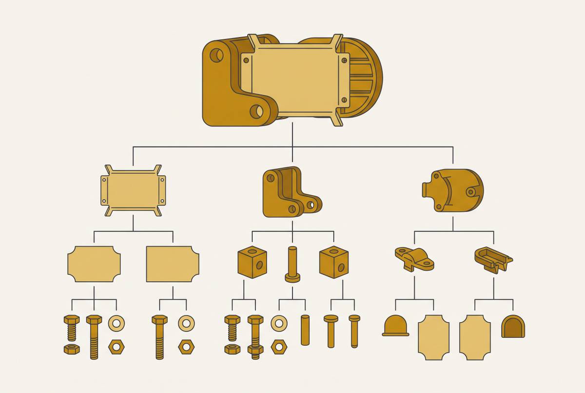
A typical mechanical assembly BOM might touch CNC milling, turning, sheet metal fabrication, 3D printing, carbon fiber layup, urethane casting, custom springs, gaskets, tube bending, wire EDM, injection molding, and die casting. Each of those processes carries its own DFM rules, its own file formats, and its own pool of capable suppliers. Fragment sourcing across all of them, and you multiply the number of places a BOM error can hide. A tolerance mismatch on a machined interface to a sheet metal bracket might not surface until both parts show up from two different vendors and simply don't fit together.
Every additional vendor is also a fresh revision control risk. Sending a drawing update to one shop and forgetting the other produces parts that don't assemble, discovered only at final assembly, which is the most expensive place to discover it.
Before the first RFQ goes out on a multi-process BOM, confirm that every line item has a defined process, a responsible source, and a complete documentation package, covering the hard parts along with the easy ones. A partner able to quote the full BOM in one package, weldments, carbon fiber, custom springs, exotic geometries included, removes a lot of that coordination overhead. It turns what would be dozens of separate clarification threads into one conversation.
The final readiness gate: checking every open item before the package leaves your desk
Open items aren't automatically disqualifying. Hidden ones are. A supplier can absolutely price alternatives for an unresolved material, coating, or tolerance, but each alternative needs its own stated assumption and its own approval path, visible rather than folded silently into a single total number.
Before the RFQ leaves your desk, walk every line item against the same questions raised throughout: Is the drawing attached and on the correct revision? Does the drawing state material and grade explicitly? Does every mating or functional feature carry a defined tolerance, with everything else left at a sane default? Is quantity clear, across every tier being quoted? Is the process assigned, and does a capable supplier exist for it?
None of this is bureaucratic overhead for its own sake. Documenting it lets you compare quotes side by side; skipping it produces a stack of numbers built on five different sets of guesses, from five different suppliers, none of whom talked to each other or to you before pricing it.