CAD File Organization Standards for BOM Submission
Messy CAD packages stall manufacturer quotes for days through preventable clarification loops.
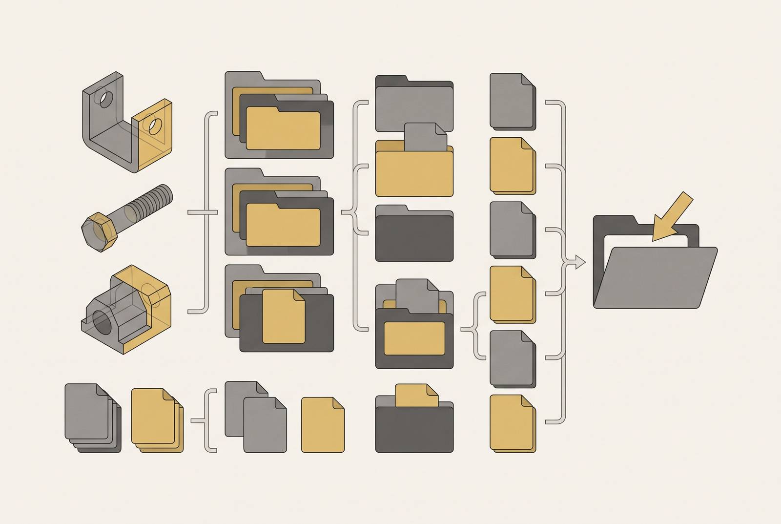
A CAD file package that's missing a revision tag, an off-format drawing, or a buried sub-assembly doesn't get rejected. It gets stuck in a clarification loop, and that loop is what turns a same-day quote into a week of email. Most of that delay is self-inflicted, built into how the files left the design team's hands, not into anything the manufacturer did wrong.
Documentation eats a real chunk of engineering time already, and CAD Interop ties manual BOM work to a big part of that drain. The same source ties manual BOM errors to a meaningful slice of engineering cost overruns. None of that even accounts for what happens after submission, when a manufacturer has to route the package through design review, drawing checks, CAM programming, machine setup, and inspection planning before a number can go out the door. Every gap in the file package stalls one of those steps. Fix the package upstream, and the whole chain moves faster.
The structural reason your design BOM and your manufacturing BOM are not the same document
The engineering BOM, or eBOM, comes straight out of CAD during design. It shows the product's functional structure: parent-child relationships, tolerances, material specs, engineering standards. It's the product as designed, full stop.
The manufacturing BOM, or mBOM, is a different animal. It's built from the eBOM but reworked for production: assembly sequences, process steps, tooling, packaging, consumables, workstation groupings. It's the product as it actually gets built on a shop floor.
The distinction runs deeper than most engineers assume. The CAD BOM describes the product from a geometrical perspective, and it isn't the same thing as the design structure, which carries the version of design intent that flows through the digital thread. That design structure is, in turn, distinct from the eBOM, which is the list of physical parts and assemblies released by product engineering. Each serves a different role in the product development process.
Here's why that matters at submission time. A design structure can be loaded with envelopes, skeletons, placeholder geometry, and reference features that mattered enormously during design, but mean nothing (or worse, cause confusion) to a manufacturer trying to quote real parts. Send the raw CAD BOM as-is, and that noise goes along with it.
So before anything gets zipped up and sent out, someone has to make a deliberate pass through the file package. Strip the design-only artifacts. Confirm every remaining line is an actual manufactured or purchased part. Check that the hierarchy reflects how the assembly gets built, not just how it happened to get modeled in CAD.
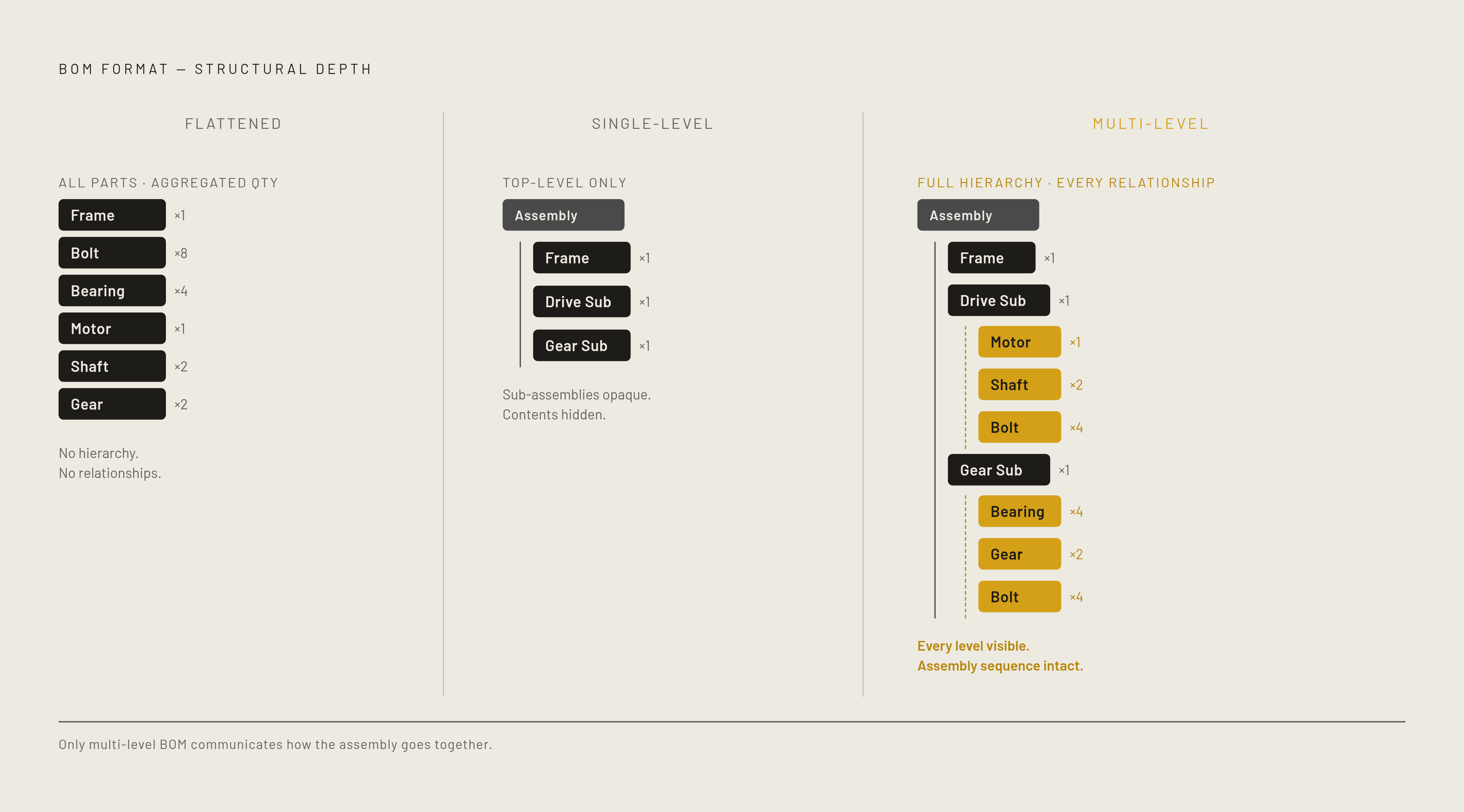
That hierarchy question splits into three formats a manufacturer might receive. A flattened BOM rolls every part into one list with quantities aggregated, with no structure. A structured single-level BOM shows only the top-level components without expanding into deeper sub-assembly relationships. A structured multi-level BOM preserves the full hierarchy, every level, every relationship intact. For any assembly with sub-assemblies, multi-level is the only format that actually communicates how the thing goes together. Anything less forces the manufacturer to reconstruct build logic from a flat list, generating clarification emails.
File format rules by process: what each manufacturing method needs to quote
The rule that covers most submissions in short: STEP for CNC, STL for 3D printing, native files only if someone explicitly asks for them. Past that baseline, format needs split by process.
CNC machining runs on STEP (.STP or.STEP), which holds solid geometry without locking the file to a specific CAD system. But the model alone can't carry tolerances, GD&T, thread callouts, surface finish, or inspection requirements, so a technical drawing in PDF has to travel alongside it. The clean flow runs: validated model, then STEP export, then technical drawing, then manufacturing specs, then quote. Skip a step, or send a model with unclear materials or missing tolerances, and the quote either slows down, comes back higher, or ends up wrong.
Sheet metal usually wants STEP plus PDF, the same pairing as CNC. DXF alone can work for flat-profile laser cutting, but only when there's no bending or forming involved. The 3D model drives programming for the laser cutter and press brake; the 2D drawing carries tolerances, material calls, and finish requirements. Neither file does the other's job.
3D printing still runs on STL. The failure mode here isn't format, it's context. An STL with no drawing, no material note, no layer orientation preference, and no finish requirement attached is a file a manufacturer has to guess at, and guessing means a delay while someone asks.
Multi-process and specialty fabrication work, things like weldments, tube assemblies, carbon fiber parts, and castings, needs both a 3D model (STEP or IGES, for cutting, forming, and machining path calculations) and a 2D dimensioned drawing (PDF or DWG, for GD&T, thread pitches, weld symbols, surface roughness). Multi-component weldments and tubular assemblies also need a structured BOM spelling out part quantities, hardware inserts, and sub-assembly hierarchy. Castings carry one extra rule: DFM sign-off and wall thickness callouts belong in the drawing package before anyone starts talking tooling. Once tooling is cut, design changes get expensive and slow, in that order.
Native CAD formats, SolidWorks parts and assemblies, Inventor files, CATIA, Siemens NX, PTC Creo, Solid Edge, Fusion, Onshape, should only go out when a manufacturer explicitly asks for them, or when parametric editing is genuinely required downstream. These files carry design history and feature-based constraints, which is exactly why they lock a downstream user to a specific CAD system. When STEP runs into translation trouble with a particular feature type, IGES, Parasolid (.X_T/.X_B), or JT are the fallback neutral formats to try.
Naming conventions and folder structure that eliminate ambiguity before it reaches a manufacturer
Three failures occur constantly, and all three are entirely preventable. A 3D model's file name doesn't match its 2D drawing's file name. An outdated drawing revision rides along next to a newer model. A linked assembly component gets left out of the zip file by accident.
The fix starts with naming. Use the part number as the primary identifier, never a generic label like "bracket_v3_FINAL," which tells a manufacturer nothing and tells the next engineer even less. Build the revision level directly into the file name, something like a P/N-REV format: 10042-B.STEP paired with 10042-B.PDF. That way, matching a model to its drawing is a glance, not a lookup. Check that part numbers are actually unique across the whole assembly; duplicates are a quoting blocker on their own. And watch for mixed units, metric parts sitting next to imperial ones with no explicit callout distinguishing them. That mix is a well-worn path to a manufacturing error that costs real money to fix.
Folder structure matters just as much as naming. A source from ProtoTech Solutions lays out this structure:
CAD Models, one 3D file per part, named to match its drawing
Round that out with an Images folder (reference photos, marked-up PDFs, whiteboard sketches that clarify intent), a Manufacturing Documents folder (past inspection records, supplier notes, process-specific instructions), a Standards folder (whichever ISO, ASME, ANSI, DIN, or ASTM standards apply), and a Previous Revisions folder, clearly labeled as archived so nobody mistakes an old file for the current one.
Before anything ships, run a completeness check on every assembly: is every referenced part file actually in the folder? Incomplete assemblies are one of the most common reasons a manufacturer sends a clarification request back instead of a quote. And keep BOM templates consistent project to project. A consistent BOM template, applied project to project, stops structural drift between one submission and the next.
BOM fields required for a multi-process assembly quote
A BOM for a custom fabrication job needs a specific set of fields, and skipping any one of them is what triggers the clarification email nobody wanted to send.
Part number comes first, and it has to match the file name and the drawing title block exactly. Revision level comes right after it, and it has to match the file's revision too; a mismatch here is one of the fastest ways to stall a quote before it starts. Part description should be functional, not generic: "6061-T6 aluminum bracket, laser-cut and bent" tells a manufacturer something useful. "Bracket" tells them nothing.
Material specification needs the alloy grade or temper or governing spec, not just "steel" or "aluminum." Quantity per assembly is straightforward, but it still gets missed. Manufacturing process matters enormously in a multi-process BOM, where one line might route to CNC and the next to sheet metal and the next to casting, each headed to a different production floor.
Standard hardware needs full callouts: fastener grade, thread spec, standard, something like "M6 × 1.0 × 16mm ISO 4762 socket head cap screw," not just "screw, qty 4." Purchased components need to be flagged as buy rather than make, with a supplier or part number reference attached. And finish or surface treatment, anodize type, plating, powder coat color and spec, needs to be settled before production planning even starts.
Assembly hierarchy belongs in the BOM structure itself. A flat parts list can't communicate build sequence or show which components need to come together before final assembly, which is exactly why multi-level structure matters for anything with sub-assemblies.
A well-organized BOM also does something less obvious: it makes cost drivers visible. Most products have a small number of assemblies that account for a disproportionate share of total spend. Surface those early, and engineering and procurement can put improvement effort where it actually pays off, instead of spreading attention evenly across parts that barely move the number.
Watch for the recurring omissions: material specs missing on custom parts, purchased components with no supplier reference or spec detail, hardware callouts missing quantity or thread spec, sub-assemblies referenced by name but never broken into their actual parts, finish requirements absent from both the BOM and the drawing. Any one of these stalls a quote on its own.
DFM as a file preparation step, not a separate review cycle
Design for manufacturability is part of preparing the files in the first place, and treating it as a separate cycle is what makes it feel optional. It's part of preparing the files in the first place, and treating it as a separate cycle is what makes it feel optional.
The cost logic backs this up hard. A Stecker Machine source states that design decisions account for 70% of a CNC part's total manufacturing cost, with the remaining 30% coming from production decisions made on the shop floor. The file package landing in a manufacturer's inbox already carries most of the cost structure, regardless of the designer's intent.
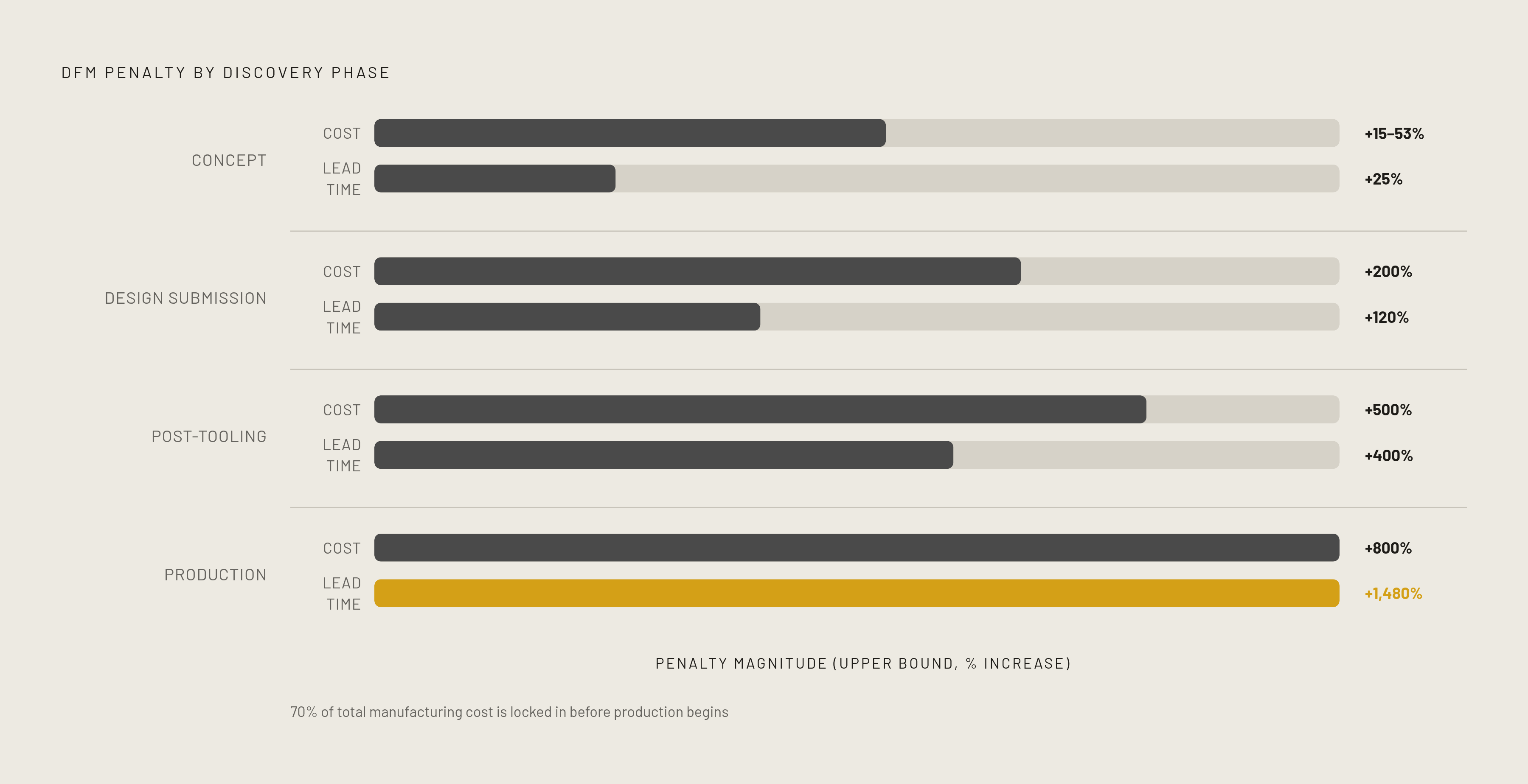
The timing makes it worse. A Modus Advanced source states that DFM issues made at the concept phase can stretch manufacturing lead times anywhere from 25% up to 1,480%, and drive costs up 15% to 800%, when a few difficult features start compounding against each other. That's a schedule-breaking problem hiding in a file that looked fine on screen.
A two-stage framework catches most of this before submission. Stage one is process selection: confirm the manufacturing process assigned to each BOM line actually fits the part's geometry, material, volume, and tolerance needs. Stage two is intra-process manufacturability: check that each part's specific features are actually achievable within the limits of whatever process it's assigned to.
The checks themselves vary by process, and they're worth running before a single file gets exported:
CNC: internal corners need a minimum radius; standard tooling can't cut a sharp internal corner, and a part submitted without that radius either gets redesigned or needs a custom tooling callout attached. Wall thickness and tool access angles need checking too. Sheet metal: bend radii, flange lengths, and hole-to-edge distances all need to sit within standard press brake and laser capabilities, and tolerances need to stay consistent between the prototype intent and the production intent. Casting: draft angles need to be present, appropriate draft angles depending on casting method, wall thickness needs to stay uniform, and fillets belong at every transition. DFM sign-off before tooling isn't optional here; post-tooling changes are expensive and slow, no way around it. 3D printing: wall thickness, overhang angle, and support requirements all need checking against the specific process and material chosen.
Run through a pre-release gate before anything gets zipped: manufacturing process, material, tolerances, wall thickness, tool access, draft, fasteners, assembly sequence, drawing notes, inspection requirements. Confirm every one of those before export.
Manufacturing partners that build instant DFM feedback into their quoting process offer a real advantage here: problems caught at quote stage, before a purchase order exists, cost nothing to fix. Problems caught after production starts cost time, money, and sometimes the part itself.
Specialty and hard-to-source parts: what their file packages need that standard machined parts do not
Most file prep guidance covers CNC and sheet metal well enough. It goes quiet on custom springs, tube bends, gaskets, weldments, and composite parts, leaving engineers to guess what a manufacturer actually needs to quote them.
Weldments and structural fabrications need a STEP file for geometry, plus a PDF drawing carrying weld symbols and finish requirements. Material and weld process requirements have to be explicit; "steel weldment" isn't a specification, it's a placeholder. An assembly drawing showing fitment context helps a manufacturer understand why a given weld joint exists and what load it's actually carrying, which matters for process selection. Any weldment with inserts, threaded features, or machined interfaces needs a structured BOM that clearly identifies each component and its role in the assembly.
Tube bending and formed tubular assemblies need a a tube routing drawing capturing bend angles and radii, all called out explicitly. A 3D model by itself isn't enough without a bending sequence or a bend radius callout attached to it. Material, wall thickness, and outer diameter need to be fully specified, and end treatment details, needs to be called out on the drawing directly.
Custom springs and gaskets carry their own spec requirements: the dimensional and material details specific to the part. These are the parts where a generic file package falls apart fastest, because the geometry alone tells a manufacturer almost nothing about how the part needs to perform.