CNC Tolerance Tradeoffs Hardware Startups Make When Speed Is the Only Metric
Reserve tight tolerances for critical fits to cut cost and rework.
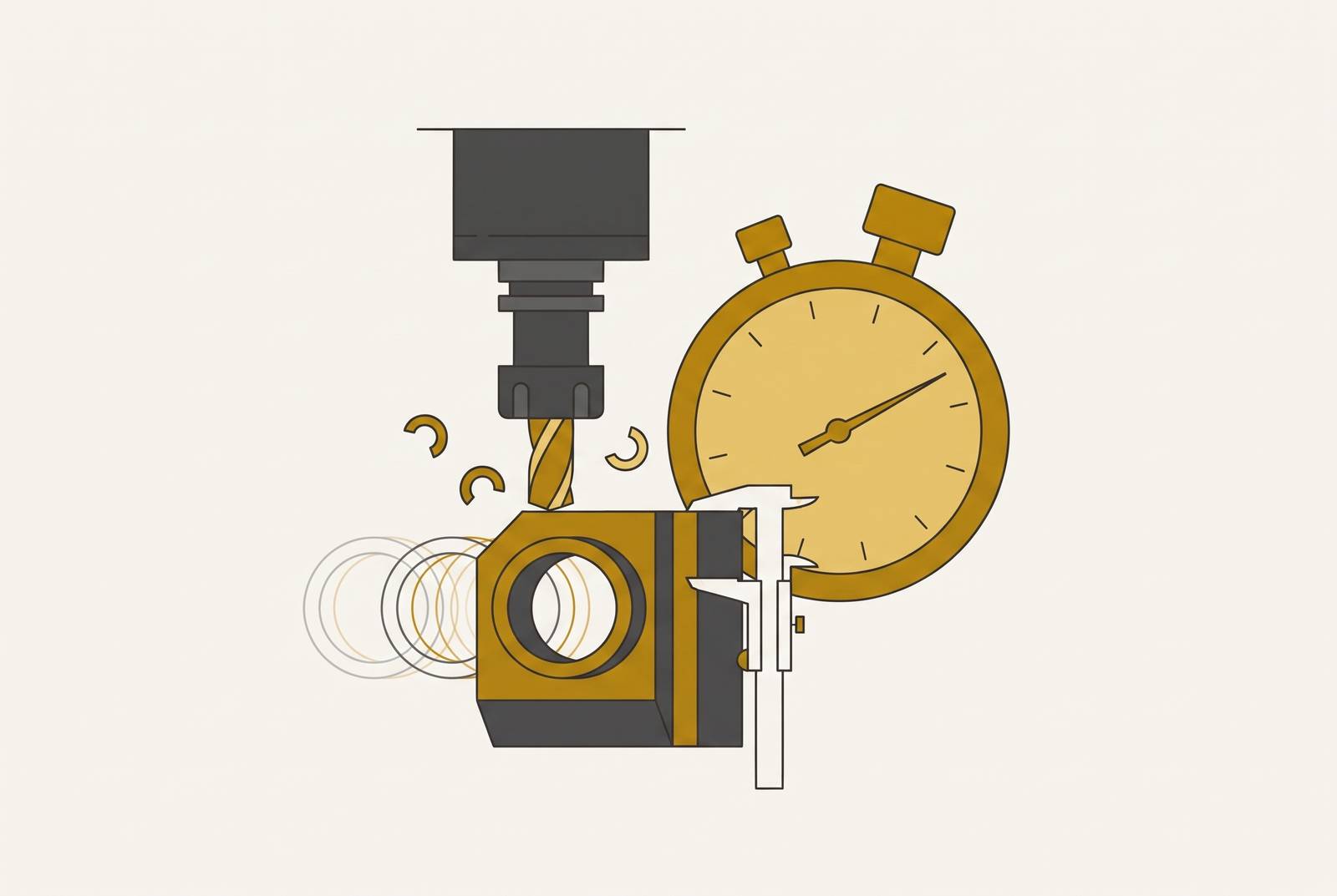
Fast-turn custom parts for hardware startups depend on selective precision. This piece explains why blanket tight tolerances slow CNC machining, inflate costs, and trigger rework. The faster path is to reserve precision for critical fits, get design-for-manufacture feedback during quoting, and coordinate the full mechanical bill of materials with a capable partner.
Why hardware startups default to CNC machining and what that rational choice sets up
CNC machining fits the constraints of early-stage hardware development. It needs none of the hard tooling that makes injection molding and casting cost so much at low volumes. A design change means revising a file rather than reworking a hardened steel mold, and a revised bracket can ship again within days. Small batches are viable from the first order. That gives teams working with limited capital a practical way to test designs before committing to larger quantities.
But the pressure to get the next part made can squeeze out the discussion that determines how long it takes to manufacture. Engineers rush to get a quote accepted and fill in tolerances without asking why each one is needed. Tight callouts look like a safe default. The decision starts with a sensible preference for fast iteration and ends with speed as the only metric.
The paradox: treating tight tolerances as "safe" actually slows everything down
A tight tolerance is a production requirement. It can call for cutting tools that cost more, slower feed rates to prevent tool deflection, extra finishing passes, and more frequent inspections. Higher rejection rates add another cost when parts miss the specified limits. Applying those requirements to non-functional surfaces buys no corresponding improvement in the product.
The objection sounds reasonable enough. Tight tolerances should make sure the part works. But a limit tighter than a feature’s functional requirement does not improve its fit or performance. A press-fit pin needs precision because its fit controls whether it holds, while an exterior cosmetic surface does not need the same dimensional control. Giving both the same specification is wasteful.
At the extreme, submicron machining of structural metal demands special tooling setup, very low feed rates, and continuous measurement. Those demands may be justified by function, but they are a costly substitute for deciding what the part needs. Blanket precision also cannot fix a fit that has been poorly thought through. Requirements that ignore function and geometry can still leave assemblies that bind, thin walls that deform, and scrap. The drawing, rather than the machine’s maximum capability, becomes the constraint.
What the tolerance tiers mean in practice and where ISO 2768 fits
ISO 2768-mK is a common general tolerance standard for CNC parts that aims to balance cost and precision. It is a useful default. General machining tolerances in the ±0.1 mm range suit clearances, cosmetic surfaces, and non-mating features. Most features do not need exceptional control. A general standard keeps the cost of those features down, while individual callouts show which dimensions need more care.
Precision tolerances in the ±0.025 mm to ±0.01 mm range suit bearing bores, shaft fits, and sealing surfaces. Here, geometry controls whether the feature works. Moving into this tier means accepting the tooling, finishing, and inspection demands needed to hold it. Ultra-precision in the ±0.001 mm range and tighter belongs to specialized work with dedicated equipment, temperature control, and metrology. It is not a routine upgrade for an ordinary enclosure.
Specialized processes have specific uses. Swiss-type turning works well for slender turned parts, while EDM can handle hardened steels and sharp internal corners, and high-speed machining can handle thin walls and detailed contours. These options make sense when mainstream CNC can no longer do the work or costs too much. They do not make every tight callout economical. Material stability, fixtures, temperature, and inspection methods still determine what a shop can achieve on a particular dimension, so an advertised capability is not a cost-neutral promise across the entire part.
How to identify which dimensions actually need tight tolerances
In practice, tolerance decisions depend on which features would cause fit, sealing, alignment, or safety failures if their dimensions drifted. A press-fit pin and its bore need a controlled fit because an overly tight fit can crack the housing, while a loose one can slip under vibration. A sealing surface needs enough flatness to prevent leaks. Bearing bores need alignment so that the shaft does not bind.
These examples give precision a job to do. Safety-critical features likewise need limits justified by their failure modes, rather than a blanket assumption that tighter is better. By contrast, clearance holes for fasteners, exterior cosmetic surfaces, non-mating walls, and general pocket depths can use standard machining tolerances when they serve no critical fit. The distinction belongs on the drawing. Annotating each tight-tolerance dimension with its functional reason tells the shop where precision effort is necessary and where the general standard is sufficient.
Geometry can make even a justified requirement expensive. Cavities deeper than roughly five times the tool diameter demand fragile, specialized tooling that can deflect, vibrate, or break. Metal walls below roughly 0.8 mm are vulnerable to deflection and chatter, although specialized tooling, fixtures, and machining strategies can reduce those effects. Small internal radii can also need smaller end mills. These features deserve attention during design-for-manufacture, or DFM, review because a realistic tolerance must account for both how the tool reaches and cuts the feature and what the assembly needs.
What over-tolerancing costs across a prototype cycle, in real terms
Skipping that functional assessment turns unnecessary precision into a recurring expense. The first bill covers the extra machining and inspection needed to meet the drawing. Rejected parts and rework cost more before the team has learned whether the design works as intended. Budget disappears without buying new design information. The cost is therefore not just a higher unit price, but less room for useful iteration.
A revision-B prototype needed because of tolerances adds time to the schedule. Engineers must revise the design, the shop must machine it again, and the team must wait for another usable part. Those are engineering hours, machine time, and calendar days that cannot be recovered by having accepted the first quote quickly. The dollar total depends on the work involved. A universal price would hide the very differences in geometry, precision, and process that drive the expense.
A successful prototype can also conceal a manufacturing problem. A hole that is occasionally out of position or a wall that deflects may become a source of repeated delays or rejected components at production quantities. Early DFM review and dimensional limits that the shop can meet help deal with those problems before they affect later runs. A design change that saves little on one prototype can save substantially more as quantities rise.
Why DFM feedback at quote time is the right intervention point
Quote time is the cheapest point to expose a tolerance problem because material has not yet been cut. Once machining begins, a problem that requires a remake has already consumed production time. The timing changes the cost of the correction. DFM input therefore belongs before final drawing approval and purchase-order placement.
CAD-to-quote platforms can bring that discussion into the upload workflow by providing immediate feedback on design alternatives. Useful feedback still depends on useful inputs. CAD geometry alone does not show why a bore needs precision or whether an exterior face has a job to do. Detailed technical drawings with tolerance callouts and functional annotations give the manufacturing partner that context. The shop can then assess tradeoffs instead of treating every strict limit as equally important.
A meaningful DFM review addresses manufacturability, cost reduction, and tolerance optimization together. It identifies difficult features, proposes changes that reduce machining time or waste, and distinguishes critical dimensions from those suited to standard tolerances. Same-day engineer support lets that review keep up with the startup. For example, a quote-stage warning about a deep pocket, an over-tight cosmetic surface, or a thin wall gives the team a chance to revise the drawing before cutting starts. The intervention need not slow quoting down to prevent a much longer rework loop.
How the multi-process BOM multiplies the tolerance problem across vendors
A mechanical bill of materials, or BOM, spanning several suppliers makes tolerance problems harder to resolve. A CNC shop, sheet metal house, spring vendor, gasket fabricator, and tube bender each work on only part of the assembly. Interface failures can cross all their boundaries. Separate shipping steps, receiving queues, and inspections then stack delays onto the work of finding out why the parts do not fit. No single supplier sees enough of the assembly to solve the whole problem alone.
The tolerance gap between processes is concrete. Sheet metal made at low volumes usually holds ±0.1 mm to ±0.2 mm on laser-cut and press-brake features, while CNC metal can hold ±0.01 mm in precision work. Standard CNC metal tolerance can be ±0.125 mm, with tighter capability at ±0.01–0.025 mm. Designing an interface requires the limits actually specified and achievable for both parts, rather than a comparison of one process’s typical result with another’s best capability.
Carbon fiber adds another interface concern because it expands differently from metal inserts, which can contribute to delamination. Dimensional precision alone does not settle that mismatch. Tightening the CNC part to compensate for uncertainty about its neighbor reverses the useful approach. The team needs to know the adjacent process’s tolerance band and specify clearances that absorb the combined variation. An integrated partner with visibility across processes can flag those conflicts during quoting, while a fragmented supplier model leaves that coordination with the startup.
That coordination burden does not end with the prototype. Higher volumes can require vendor requalification and lead-time renegotiation across the fragmented BOM, bringing interface risks back into the discussion. Integrated facilities with agile production cells can handle that shift without making the startup set up all the work of coordinating separate vendors again.
What should hardware startups look for in a fast-turn custom-parts partner?
A capable partner should be able to quote, make, inspect, and ship the full mechanical BOM under one quality system. Fabrication, finishing, and assembly can then be reviewed together. One quote, one purchase order, and one shipment remove the repeated receiving steps and inter-vendor handoffs that complicate a fragmented order. The DFM discussion can address the interfaces as well as the individual parts.
A partner handling CNC milling, turning, sheet metal, 3D printing, carbon fiber, custom springs, gaskets, tube bending, and wire EDM can examine tolerance stack-ups across the assembly before production. Coverage alone is not enough, though. Dedicated project engineers, proactive issue identification, and regular progress updates give the startup a clear point of contact and visibility before shipment. Inspection under the same quality system connects those discussions to the parts that leave the facility.
For a team seeking custom machined parts in under a week, a fast quote is not sufficient evidence that the complete job will arrive on time. The team should look for quote-stage DFM, same-day engineering support, coverage of the processes it needs, and inspection and shipping that are coordinated. A tight deadline makes those capabilities more valuable. It leaves less room to discover, after separate orders are underway, that the mating parts were designed around incompatible assumptions.
The goal is the right specification on each functional feature, made through a coordinated manufacturing plan with a partner that inspects every part before shipment. Hardware teams that annotate critical tolerances, resolve DFM questions during quoting, and consolidate the BOM remove avoidable work from the schedule. Speed and precision are not enemies. Unnecessary precision and fragmented responsibility are what turn a quick order into a slow development cycle.